DHCP Server setup in CISCO Packet Tracer#
Introduction: Configuring a DHCP server is a fundamental skill for network administrators and engineers. In this blog post, we’ll explore three video tutorials that walk you through DHCP server configuration using CISCO Packet Tracer. Whether you’re dealing with a single switch, a router-based setup, or a complex network with multiple switches, you’ll find step-by-step instructions to help you get started.
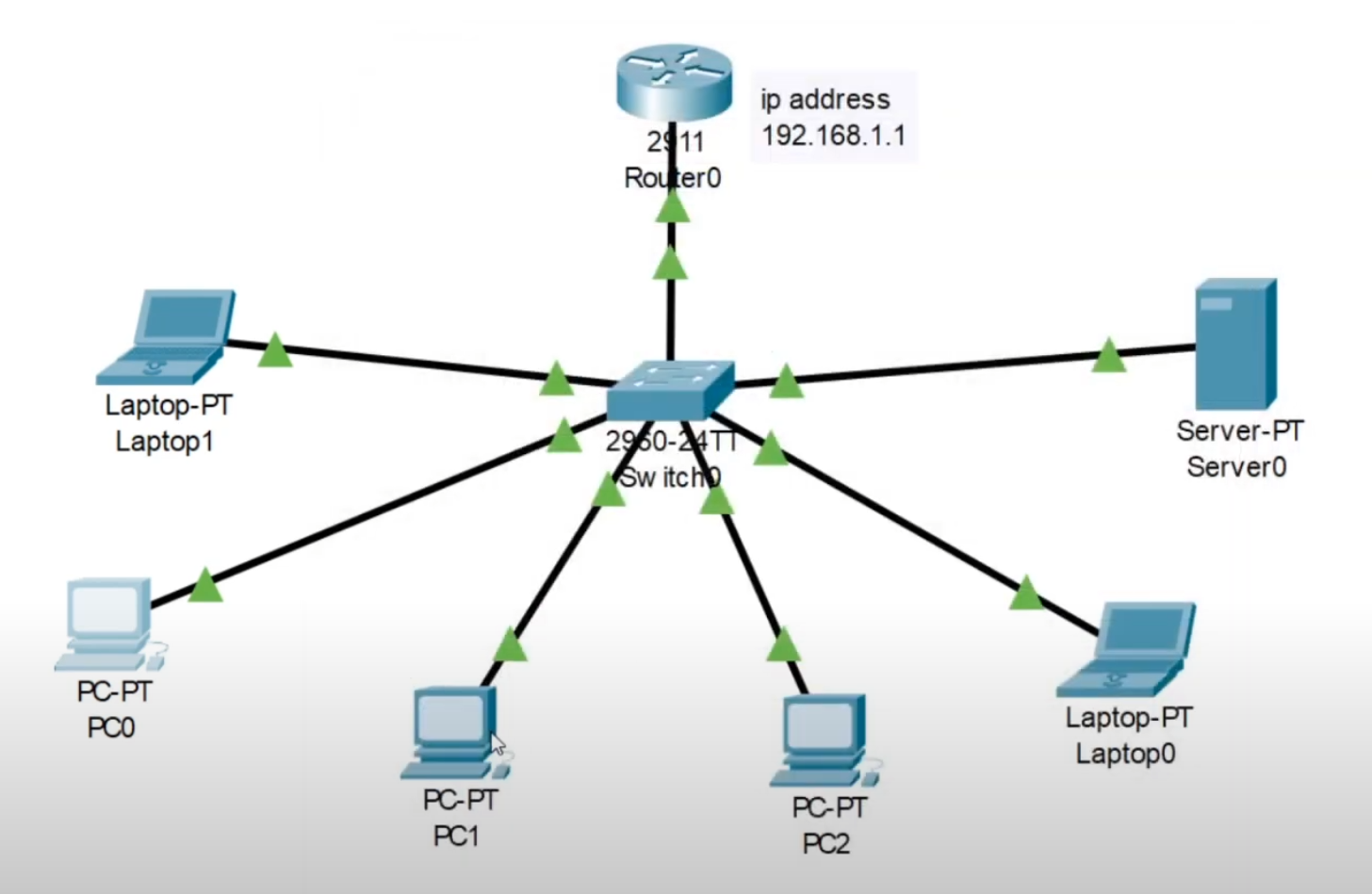
Video 1: DHCP Server Configuration with a Single Switch#
In this video, you’ll learn how to set up a DHCP server within CISCO Packet Tracer using a single switch. This tutorial simplifies the process, making it easy for beginners to understand and implement.
Here are the steps:#
Enable the CLI.
Enter global configuration mode:
conf tConfigure the switch interface:
int g0/0Assign an IP address and subnet mask to the interface:
ip address 192.168.1.1 255.255.255.0Enable the interface:
no shutdownSave the configuration:
do write memoryExit interface configuration mode:
exitConfigure the DHCP pool:
ip dhcp pool ABC-POOLDefine the network:
network 192.168.1.0 255.255.255.0Set the default router:
default-router 192.168.1.1Specify the DNS server:
dns-server 192.168.1.254
Exit the DHCP pool configuration:
exitSave the configuration again:
write memory
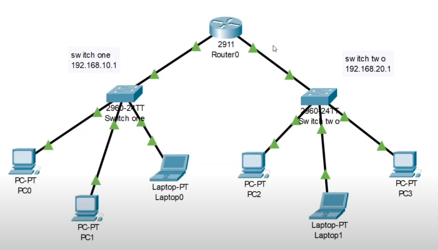
Video 2: Router-Based DHCP Server Configuration#
In the second video, you’ll discover how to configure a router to manage DHCP within CISCO Packet Tracer. This approach allows you to automatically assign IP addresses to connected devices.
Here are the steps:#
Enable the CLI.
Enter global configuration mode:
conf tConfigure the router’s first interface:
int g0/0Assign an IP address and subnet mask:
ip address 192.168.10.1 255.255.255.0Enable the interface:
no shutdownSave the configuration:
do write memoryCreate a DHCP pool for the first switch:
ip dhcp pool switch1Define the network:
network 192.168.10.1 255.255.255.0
Exit the pool configuration:
exitConfigure the router’s second interface:
int g0/1Assign an IP address and subnet mask:
ip address 192.168.20.1 255.255.255.0Enable the interface:
no shutdownSave the configuration:
do write memoryCreate a DHCP pool for the second switch:
ip dhcp pool switch2Define the network:
network 192.168.20.1 255.255.255.0
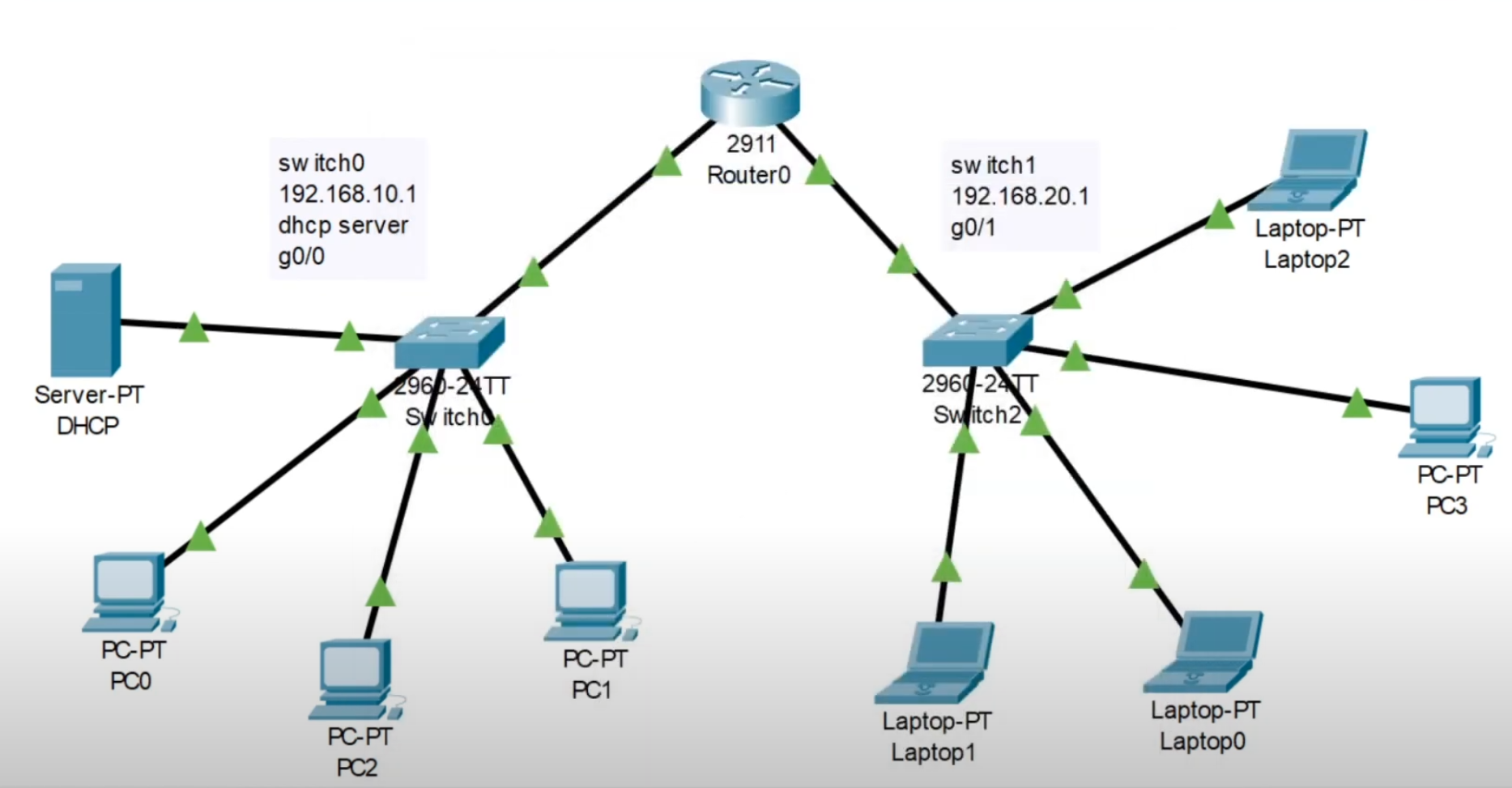
Video 3: DHCP Server Configuration with Multiple Switches#
The third video guides you through setting up a home network with multiple switches and a dedicated DHCP server. This scenario mimics a more complex real-world environment.
Follow these steps-#
Start by configuring the DHCP server:
Set the server’s static IP address to
192.168.10.2(the default gateway for switch 1)Create a DHCP pool for the first switch, naming it “SwitchONE,” with a default gateway of
192.168.10.1and a starting IP of192.168.10.3, allowing up to 20 addresses.Repeat the DHCP pool creation for the second switch, starting with 2.2 as it has no server.
Configure the router:
Enter global configuration mode:
conf tConfigure the first interface:
int g0/0Assign the IP address and specify the helper address (the server address):
ip address 192.168.10.1 255.255.255.0ip helper-address 192.168.10.2Enable the interface:
no shutdownSave the configuration:
do write memory
Configure the second interface of the router in a similar fashion.
Conclusion:#
Configuring DHCP servers is an essential skill for managing IP address allocation within a network. These three videos, ranging from single switches to complex network setups, provide comprehensive guidance on DHCP server configuration using CISCO Packet Tracer. Whether you’re a novice or an experienced network administrator, these tutorials will help you gain the expertise you need. Happy networking!