1 – Basic Networking#
This tutorial is the first in a series designed to introduce you to networking concepts using Cisco Packet Tracer. It will guide you through creating a simple network with two PCs connected via a switch, configuring both IPv4 and IPv6 addresses, and testing connectivity using the ping command.
Find the CISCO pkt files in the repo -
Creating a Simple Network with Two PCs and a Switch in Cisco Packet Tracer#
In this first tutorial, we will step through how to build a basic local network using Cisco Packet Tracer. This network will consist of two end devices (PCs) connected through a switch. We will assign both IPv4 and IPv6 addresses manually and test communication between the devices using the ping command.
This exercise introduces core networking concepts such as MAC and IP addressing, switching, and address-based communication. It is suitable for beginners who are just getting started with Packet Tracer or networking in general.
Part 1 – Building the Network Topology#
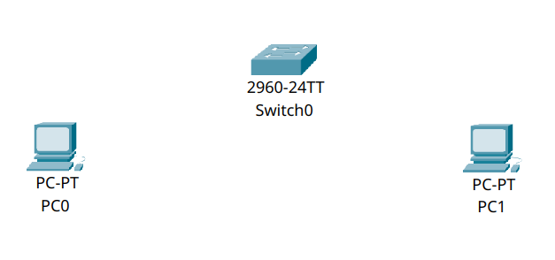
The network topology we are going to build is very simple:
\[PC0] —— \[Switch] —— \[PC1]
This is often referred to as a point-to-point LAN segment, although it involves a switch rather than a direct cable connection. It represents the kind of connection you’d see in a small office or lab environment.
Step 1.1 – Add Devices to the Workspace#
Launch Cisco Packet Tracer.
At the bottom left, open the End Devices panel.
Drag PC0 and PC1 into the main canvas.
Open the Switches panel and drag a 2960 switch into the canvas.
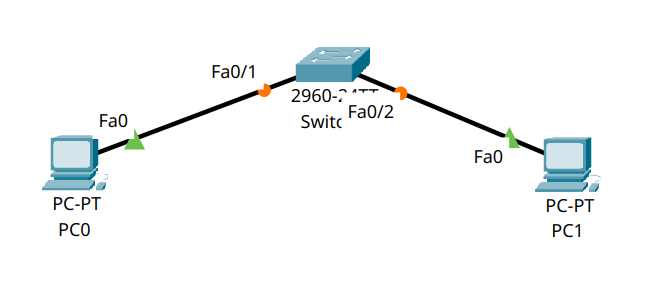
Step 1.2 – Connect Devices Using Cables#
From the Connections bar (lightning bolt icon), choose the Copper Straight-Through cable.
Click on PC0 → select
FastEthernet0, then click on Switch0 → selectFastEthernet0/1.Repeat the process for PC1, but connect it to
FastEthernet0/2on the switch.
Part 2 – Configuring IPv4 Settings#
In this section, we will manually configure IPv4 addresses for both PCs so they are part of the same subnet and able to communicate directly. We’ll use the graphical interface (GUI) on each device to assign IP addresses.
This configuration is essential to allow the devices to recognise and communicate with each other across the local network.
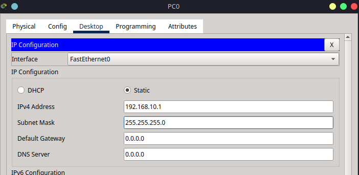
Step 2.1 – Assign IPv4 Address to PC0 (via GUI)#
Click on PC0 to open its configuration window.
Navigate to the Desktop tab and select IP Configuration.
Under the IPv4 section, set the following values:
IP Address:
192.168.10.1Subnet Mask:
255.255.255.0Leave the Default Gateway field blank
This assigns PC0 a static IP address in the 192.168.10.0/24 network.
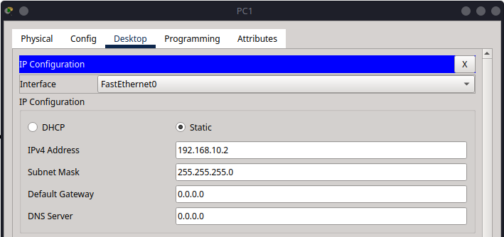
Step 2.2 – Assign IPv4 Address to PC1 (via GUI)#
Click on PC1, go to the Desktop tab, and open IP Configuration.
Enter the following IPv4 settings:
IP Address:
192.168.10.2Subnet Mask:
255.255.255.0Leave the Default Gateway field blank
By assigning an IP address in the same subnet, PC1 is now able to communicate directly with PC0.
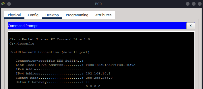
Verifying IP Configuration#
To confirm the IP settings on each PC:
Go to the Desktop tab on each PC.
Open Command Prompt.
Type the following command:
ipconfig
Part 3 – Testing IPv4 Communication#
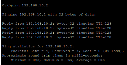
Step 3.1 – Ping from PC0 to PC1#
On PC0, go to the Desktop tab, then open the Command Prompt.
Enter the following command:
ping 192.168.10.2
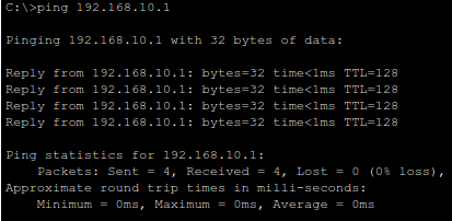
You should receive four reply messages. This confirms that the connection is working over IPv4.
If you see timeouts:
Check the IP address and subnet mask on both PCs
Ensure the cables are properly connected
Confirm the switch is powered on and all ports are active
Part 4 – Configuring IPv6 Settings#
IPv6 allows for a much larger address space and is increasingly important for modern networks. Unlike IPv4, IPv6 uses hexadecimal and colons to represent addresses.
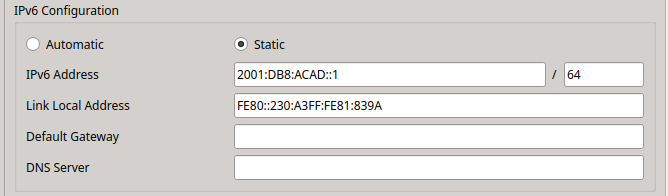
Step 4.1 – Assign IPv6 Address to PC0#
In the IP Configuration window on PC0, scroll to the IPv6 Configuration section:
IPv6 Address:
2001:db8:acad::1Prefix Length:
64
This corresponds to the address range 2001:db8:acad::/64, which is a common documentation/test prefix.
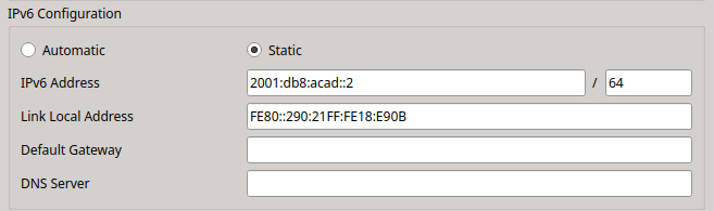
Step 4.2 – Assign IPv6 Address to PC1#
Do the same for PC1:
IPv6 Address:
2001:db8:acad::2Prefix Length:
64
Now both devices are on the same IPv6 subnet.
Part 5 – Testing IPv6 Communication#
Step 5.1 – Ping Using IPv6#
On PC0, open the Command Prompt again.
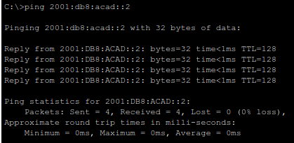
Use the
pingcommand with the IPv6 address:ping 2001:db8:acad::2
This will test whether PC0 can reach PC1 using IPv6. You should again receive successful replies.
Additional Notes#
MAC Addresses: Although not configured here, each PC has a unique MAC address. The switch learns which MAC is on which port dynamically.
ARP vs NDP: For IPv4, communication begins with ARP (Address Resolution Protocol); for IPv6, it uses NDP (Neighbour Discovery Protocol).
No Routing Required: Because this is a single subnet, no router is required for communication.
Summary#
In this tutorial, you learned how to:
Build a simple LAN with two PCs and a switch in Cisco Packet Tracer
Manually configure and verify IPv4 and IPv6 addresses
Use the
pingcommand to test network connectivity