2 – Configuring Multi-Switch Communication#
This tutorial is the second in a series focused on Cisco networking concepts, specifically using Cisco Packet Tracer. In this lesson, we will connect two PCs through two switches, demonstrating key concepts such as port activation, MAC address learning, and VLAN configuration.
Find the CISCO pkt files in the repo -
Connecting Two PCs Through Two Switches in Cisco Packet Tracer#
In this tutorial, we’ll explore how to connect two end devices (PCs) through a chain of two switches. While this setup does not require IP routing, it introduces important switching concepts such as port activation, MAC address learning, and proper VLAN configuration.
This scenario is common in enterprise environments where multiple switches form the backbone of a local area network (LAN). Understanding how switches interact is essential to building reliable and scalable network infrastructures.
Part 1 – Network Topology Overview#
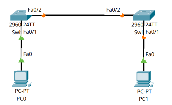
We will build the following topology:
\[PC0] ── \[Switch0] ── \[Switch1] ── \[PC1]
Each device will be configured with a static IP address in the same subnet, and we’ll ensure the switches allow Layer 2 traffic to pass between them seamlessly.
Part 2 – Device Placement and Cabling#
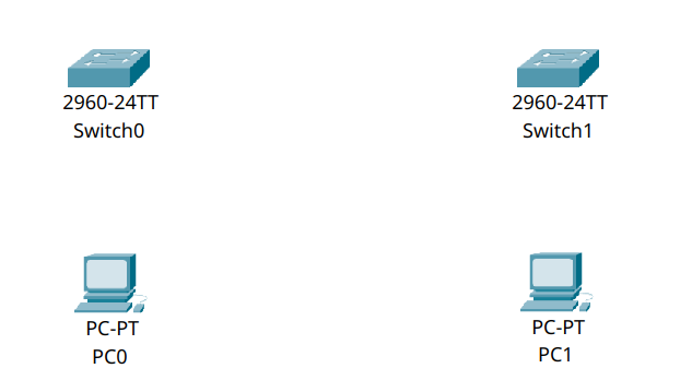
Step 2.1 – Add Devices#
Drag two PCs (e.g. PC0 and PC1) into the workspace.
Add two switches (Switch0 and Switch1, model 2960 recommended).
Step 2.2 – Connect Devices#
Use Copper Straight-Through cables to make the following connections:
PC0 → Switch0, using
FastEthernet0Switch0 → Switch1, using
FastEthernet0/24on both switchesSwitch1 → PC1, using
FastEthernet0
Part 3 – Configure IPv4 Addresses#
We will assign static IP addresses to both PCs.
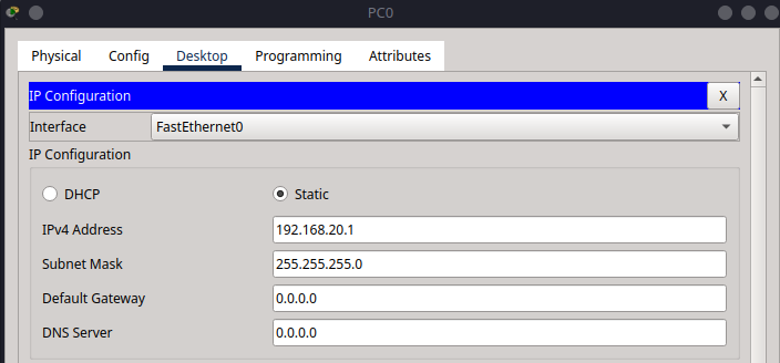
Step 3.1 – PC0 IPv4 Settings#
Click on PC0.
Go to Desktop → IP Configuration.
Enter:
IP Address:
192.168.20.1Subnet Mask:
255.255.255.0
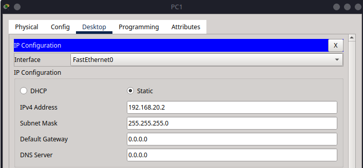
Step 3.2 – PC1 IPv4 Settings#
Click on PC1.
Go to Desktop → IP Configuration.
Enter:
IP Address:
192.168.20.2Subnet Mask:
255.255.255.0
Part 4 – Configuring Switch Ports#
By default, Cisco switches have all ports assigned to VLAN 1 and are administratively up, but sometimes ports need to be explicitly activated.
We will:
Confirm all ports are operational
Ensure all involved ports are assigned to the same VLAN
Manually enable interfaces if needed
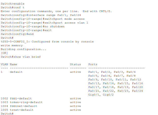
Step 4.1 – Configure Switch0#
Click on Switch0, go to the CLI tab.
Enter the following commands:
enable
configure terminal

interface range fa0/1, fa0/24
switchport mode access
switchport access vlan 1
no shutdown
exit

end
write memory
This ensures:
Port
fa0/1(to PC0) andfa0/24(to Switch1) are activeBoth are assigned to VLAN 1

Step 4.2 – Configure Switch1#
Click on Switch1, go to the CLI tab.
Enter:
enable
configure terminal

interface range fa0/1, fa0/24
switchport mode access
switchport access vlan 1
no shutdown
exit

end
write memory
Again:
Port
fa0/1(to PC1) andfa0/24(from Switch0) are activeVLAN 1 is used for untagged traffic across the switches
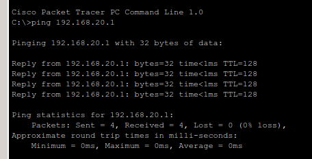
Part 5 – Testing Connectivity#
To verify that switching is working:
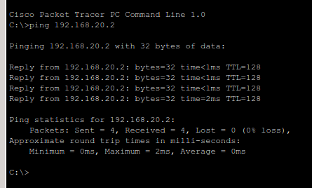
On PC0, open the Command Prompt.
Ping PC1:
ping 192.168.20.2
You should receive successful replies.
If not, double-check:
All interfaces on both switches are no shutdown
All ports are on the same VLAN
PC IP addresses are correct and in the same subnet
Cabling is correct
Summary#
In this tutorial, you have:
Connected two PCs across two switches
Assigned static IPv4 addresses in the same subnet
Verified port activation and VLAN assignment on switches
Successfully tested communication across a multi-switch setup