5 – Understanding ARP in Packet Tracer#
This tutorial builds upon Tutorial 4 – Inter-VLAN Routing and focuses on a key Layer 2 concept: the Address Resolution Protocol (ARP). ARP is essential for devices to communicate within a local network by resolving IP addresses to MAC addresses.
Part 1 – What is ARP?#
When a device wants to communicate with another on the same network, it needs to know the MAC address associated with the destination IP. If it doesn’t know it, the device sends out an ARP Request asking, “Who has this IP?” The device with the matching IP replies with an ARP Reply containing its MAC address.
This process is automatic and often hidden behind the scenes – but we can observe it directly using Packet Tracer.
Part 2 – Use the Existing Network#
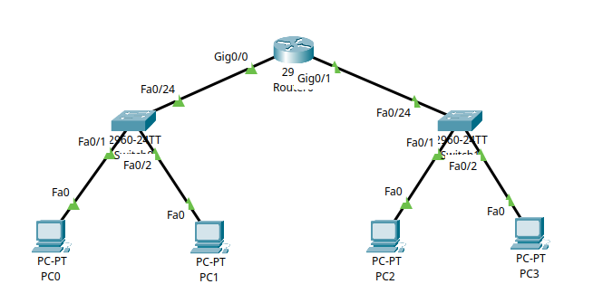
We will use the network built in Tutorial 4. You should have:
PC0 and PC1 in VLAN 10 (Subnet
192.168.10.0/24)PC2 and PC3 in VLAN 20 (Subnet
192.168.20.0/24)A router (Router0) configured with:
Gig0/0→192.168.10.1Gig0/1→192.168.20.1
Ensure all PCs have their IP settings configured and can ping each other as per the end of Tutorial 4.
Part 3 – Checking the ARP Table#
Step 3.1 – Viewing ARP on a PC#
To check the ARP table on a PC:
Click on PC0
Go to Desktop → Command Prompt
Type the following:
arp -a
This will show the current ARP table. If the table is empty, no local communication has happened yet.
Step 3.2 – Triggering ARP with a Ping#
Now let’s populate the ARP table:
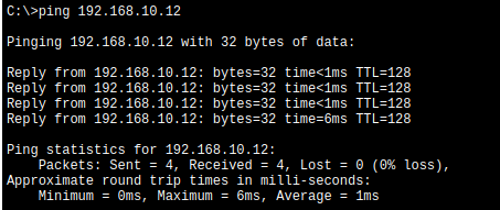
From PC1, ping PC2:
ping 192.168.10.12
Then run:
arp -a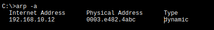
You’ll now see the MAC address of PC2 in the table, mapped to its IP.
You can repeat this process on PC2 and PC3, or try pinging across VLANs (e.g., PC1 → PC3) to see the router’s MAC appear in the table instead of the end device’s MAC.
Part 4 – ARP Table on the Router#
You can also view ARP entries on the router:
Click on Router0
Go to the CLI tab
Enter privileged mode:
enableRun:
show ip arp
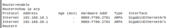
This will display the ARP table of the router, including connected devices.
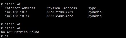
Part 5 – Clearing the ARP Table#
Step 5.1 – On a PC#
To clear the ARP cache on a PC in Packet Tracer:
Click on PC0
Go to Desktop → Command Prompt
Type:
arp -d
Then check with:
arp -a
Part 6 – Observing ARP in Simulation Mode#
To clearly observe the ARP process in Packet Tracer’s Simulation Mode, follow these steps:
Note on Simulation Mode
You can refer back to tutorial 3 for a refresher on using Simulation Mode in Packet Tracer.
Switch to Simulation Mode: Click the Simulation button at the bottom right corner of Packet Tracer.
Clear the ARP Cache: On PC1, open the Desktop → Command Prompt and type:
arp -dThis ensures the ARP table is empty, so you’ll see the ARP process from the start.
Send a Ping: From PC1, ping PC2:
ping 192.168.10.12
Step Through the Simulation: Use the Capture / Forward button to advance packet by packet.
You’ll observe:
An ARP Request packet broadcast to the network
An ARP Reply packet sent back from PC2
The subsequent ICMP Echo Request and Reply (the actual ping)
This process lets you visualise how ARP works before any communication occurs.
Summary#
In this tutorial, you learned:
What ARP is and how it enables IP-to-MAC resolution
How to check the ARP table on PCs and routers
How to clear ARP entries and repopulate them
How to visualise ARP packets in Packet Tracer using Simulation Mode