4 – Inter-VLAN Routing (Router-on-a-Stick)#
This tutorial is the fourth in our series on Cisco Packet Tracer, focusing on inter-VLAN routing using a Router-on-a-Stick (ROAS) configuration. This method allows a single router to route traffic between multiple VLANs by using subinterfaces.
Find the CISCO pkt files in the repo -
Using Subinterfaces to Route Between VLANs in Cisco Packet Tracer#
In this tutorial, we’ll walk through a complete setup of inter-VLAN routing using a Router-on-a-Stick (ROAS) topology. This is a core concept in modern enterprise networks, where multiple VLANs (Virtual LANs) are used to segment traffic, and a single router is used to enable communication between them.
We will:
Create VLANs for different groups of users
Assign switchports to VLANs
Use router subinterfaces to route between VLANs
Verify everything with ping and
ipconfig
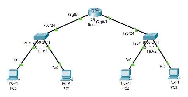
Part 1 – Understanding the Topology#
This lab simulates a small business network divided into two departments, each with its own VLAN:
Department A (VLAN 10): PC1 and PC2
Department B (VLAN 20): PC3 and PC4
The network topology is designed to demonstrate how inter-VLAN routing is achieved using a single router (Router-on-a-Stick). The physical and logical connections are as follows:
           +---------+         +---------+         +---------+
PC0 -------|         |         |         |         |         |------- PC2
           | Switch0 |--- fa0/1| Router0 |fa0/2 ---| Switch1 |
PC1 -------|         |         |         |         |         |------- PC3
           +---------+         +---------+         +---------+
Key Concepts Covered#
VLANs (Virtual LANs): Used to logically segment the network at Layer 2, isolating broadcast domains and improving security and performance.
Router Subinterfaces: Logical interfaces configured on a single physical router port, each assigned to a specific VLAN, allowing the router to route traffic between VLANs.
Part 2 – Device Setup and Cabling#
Step 2.1 – Selecting and Placing Devices#
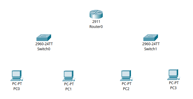
In Cisco Packet Tracer, select and place the following devices on your workspace:
Router: Cisco 2911 (or a similar model that supports subinterfaces)
Switches: Two Cisco 2960 switches (Switch0 and Switch1)
End Devices: Four generic PCs (PC0, PC1, PC2, PC3)
Labelling and Placement Guidelines#
Place Switch0 and Switch1 near the center of your workspace.
Position Router0 between the two switches to represent its central role in routing.
Place PC0 and PC1 near Switch0.
Place PC2 and PC3 near Switch1.
Clearly label each device for easy identification.
Step 2.2 – Cabling the Network#
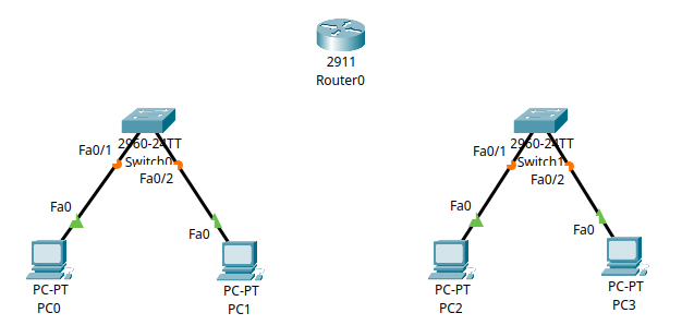
Connecting End Devices to Switches#
Use Copper Straight-Through cables for all device-to-switch connections:
PC0 to
fa0/1on Switch0PC1 to
fa0/2on Switch0PC2 to
fa0/1on Switch1PC3 to
fa0/2on Switch1
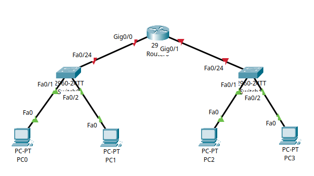
Connecting Switches to Router#
Use Copper Straight-Through cables for switch-to-router connections:
Switch0
fa0/24to Router0gig0/0Switch1
fa0/24to Router0gig0/1
Note
For clarity and future expansion, I recommend connecting the switch to the router using the last available port on the switch (for example, fa0/24). This keeps the lower-numbered ports free for connecting PCs and other end devices.
Cabling Tips#
Double-check that each PC is connected to the correct switch port.
Avoid using crossover cables; straight-through is standard for these connections in Packet Tracer.
Note
Proper device placement and accurate cabling are crucial for the success of the lab. If you encounter connectivity issues later, revisit this section to verify your setup.
Part 3 – VLAN Configuration and Port Assignment#
In this section, you’ll configure VLANs, assign access ports, and save the configuration on each switch.
On Switch0 (Department A)#
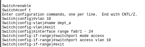
Enter privileged EXEC mode and global configuration mode:
enable
configure terminal
Create VLAN 10 and name it:
vlan 10
name Dept_A
exit
Assign all access ports on the switch (e.g.,
fa0/1tofa0/24) to VLAN 10:interface range fa0/1 - 24 switchport mode access switchport access vlan 10 exit exit write memory
Verify VLAN configuration:
show vlan brief
On Switch1 (Department B)#
Enter privileged EXEC mode and global configuration mode:
enable
configure terminal
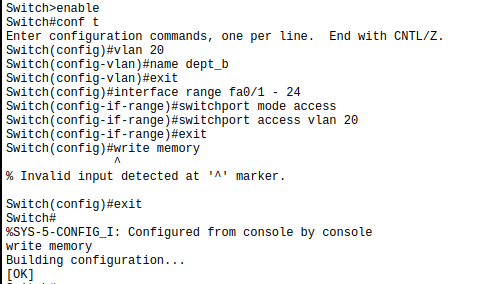
Create VLAN 20 and name it:
vlan 20
name Dept_B
exit
Assign all access ports on the switch (e.g.,
fa0/1tofa0/24) to VLAN 20:interface range fa0/1 - 24 switchport mode access switchport access vlan 20 exit exit write memory
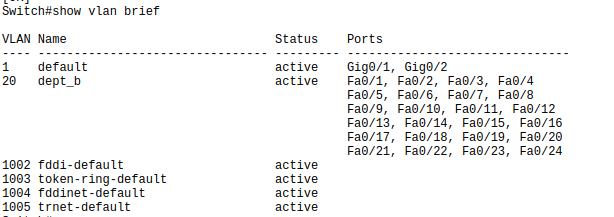
Verify VLAN configuration:
show vlan brief
Note
If you encounter issues later, revisit these steps to confirm your VLAN and port assignments are correct.
Part 4 – Router Interface Configuration (No Subinterfaces)#
Instead of using subinterfaces and trunk links (we will cover this in a later tutorial), we configure one physical router interface per VLAN. Each router interface connects to a switch access port that carries a single VLAN.
Step 4.1 – Configure Router Interfaces on Router0#
Start by entering into the cli of Router0:
enable
conf t
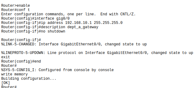
For VLAN 10 (Department A):#
Then configure the interface for VLAN 10:
interface gig0/0
ip address 192.168.10.1 255.255.255.0
description Dept_A_Gateway
no shutdown
exit

end
write memory
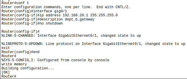
For VLAN 20 (Department B):#
Next, configure the interface for VLAN 20:
conf t
interface gig0/1
ip address 192.168.20.1 255.255.255.0
description Dept_B_Gateway
no shutdown
exit

end
write memory
No VLAN encapsulation is needed because each interface handles only one VLAN.
Part 5 – Configure PC IP Settings#
Each PC needs a static IP address and default gateway to enable communication within and across VLANs.
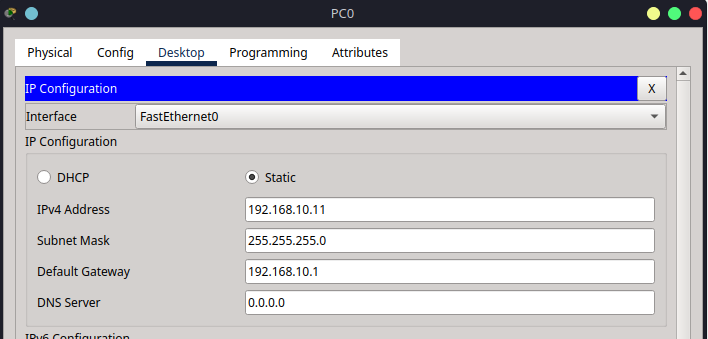
Step 5.1 – Configure PC0 IPv4 Settings#
Click on PC0.
Navigate to Desktop → IP Configuration.
Enter the following:
IP Address:
192.168.10.11Subnet Mask:
255.255.255.0Default Gateway:
192.168.10.1
Step 5.2 – Repeat for the Other PCs#
Use the table below to configure the remaining devices:
PC |
VLAN |
IP Address |
Subnet Mask |
Default Gateway |
|---|---|---|---|---|
PC0 |
VLAN 10 |
|
|
|
PC1 |
VLAN 10 |
|
|
|
PC2 |
VLAN 20 |
|
|
|
PC3 |
VLAN 20 |
|
|
|
Repeat Step 5.1 on each PC, entering the values from the table above.
All PCs should now be configured with their respective IP addresses and gateways, and all arrows should be green, indicating successful configuration.
Part 6 – Verification and Troubleshooting#
Step 6.1 – Ping Tests#
After completing all configurations, verify connectivity between devices to ensure inter-VLAN routing is working as expected.
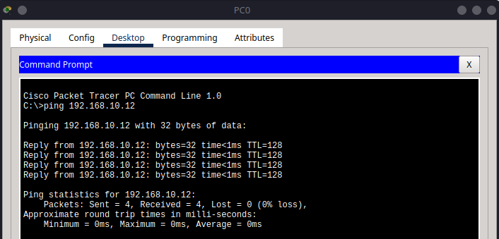
1. Test Intra-VLAN Connectivity#
PC0 → PC1:
Open the command prompt on PC0 and ping PC1’s IP address (192.168.10.12).ping 192.168.10.12
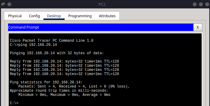
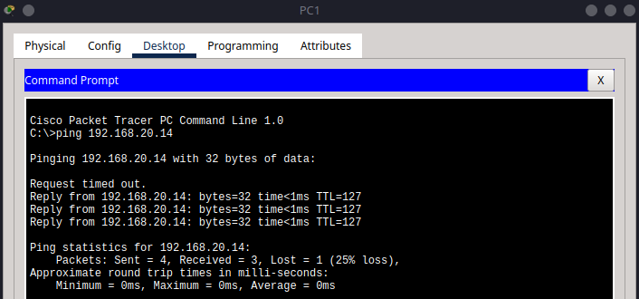
PC2 → PC3:
On PC2, ping PC3’s IP address (192.168.20.14).ping 192.168.20.14
2. Test Inter-VLAN Connectivity#
PC0 → PC2:
On PC0, ping PC2’s IP address (192.168.20.13).ping 192.168.20.13
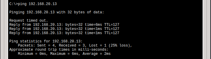
Note here how the first ping failed, but subsequent pings were successful. This is a common behaviour in networks due to the initial ARP request (which we will cover in a later tutorial).
PC1 → PC3:
On PC1, ping PC3’s IP address (192.168.20.14).ping 192.168.20.14
PC3 → PC0:
On PC3, ping PC0’s IP address (192.168.10.11).ping 192.168.10.11

Note
If any ping fails for all 4 attempts, double-check IP configurations, VLAN assignments, and router interface settings.
Summary#
In this tutorial, you accomplished the following:
Created and named VLANs to logically segment the network for different departments.
Assigned switchports to VLANs to ensure devices are grouped correctly.
Configured trunk and access links between switches and the router to enable VLAN traffic flow.
Set up router interfaces with appropriate IP addresses to serve as gateways for each VLAN.
Configured static IP addresses and gateways on all PCs to match their respective VLANs.
Verified both intra-VLAN and inter-VLAN connectivity using ping tests and troubleshooting commands.
By following these steps, you demonstrated how to implement basic inter-VLAN routing in Cisco Packet Tracer using separate router interfaces for each VLAN.