14 – DHCP Server Configuration in Cisco Packet Tracer#
This tutorial is the fourteenth in our Cisco Packet Tracer series and introduces the configuration of a DHCP (Dynamic Host Configuration Protocol) server. DHCP automates IP address assignment, simplifying host configuration in networks of all sizes.
We’ll build a basic network with one router, two switches, six PCs, and one DHCP server. The DHCP server will dynamically assign IP addresses to all PCs in the network.
Find the CISCO pkt files in the repo -
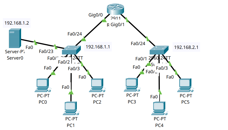
Part 1 – Network Topology Overview#
This network includes:
One router (R0)
Two switches (S0, S1)
Six PCs (PC0–PC5)
One server (Server0) acting as the DHCP server, connected to Switch 0
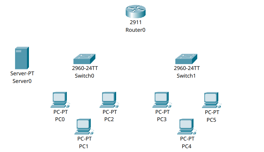
Part 2 – Device Placement and Cabling#
Step 2.1 – Add Devices to the Workspace#
From Network Devices and End Devices, place:
1 Router (2911)
2 Switches (2960)
6 PCs (PC0–PC5)
1 Server (Server0)
Label as follows:
Router: R0
Switches: S0, S1
Server: Server0 (DHCP)
PCs: PC0–PC5
Step 2.2 – Cabling#
Use Copper Straight-Through connections:
From |
To |
Port |
|---|---|---|
PC0–PC2 |
S0 |
fa0/1–fa0/3 |
Server0 |
S0 |
fa0/23 |
PC3–PC5 |
S1 |
fa0/1–fa0/3 |
S0 |
R0 |
fa0/24 → gig0/0 |
S1 |
R0 |
fa0/24 → gig0/1 |
Part 3 – IP Addressing Plan#
We’ll configure two subnets, one per switch:
Subnet |
Range |
Subnet Mask |
|---|---|---|
192.168.1.0 |
Switch S0 (VLAN1) |
255.255.255.0 |
192.168.2.0 |
Switch S1 (VLAN2) |
255.255.255.0 |
Router interfaces:
Device |
Interface |
IP Address |
|---|---|---|
R0 |
gig0/0 |
192.168.1.1 |
R0 |
gig0/1 |
192.168.2.1 |
The DHCP server will provide addresses within:
192.168.1.10–192.168.1.100 for VLAN 1 (Switch 0)
192.168.2.10–192.168.2.100 for VLAN 2 (Switch 1)
Part 4 – Configuration#
Now we will configure the DHCP server and router interfaces to enable automatic IP address assignment. It’s important to ensure the DHCP server is reachable from both VLANs and therefore we will set it up first.
Step 4.1 – Configure the DHCP Server#
Click on Server0
Go to the Desktop tab → Select IP Configuration
Set the following values:
IPv4 Address:
192.168.1.2Subnet Mask:
255.255.255.0Default Gateway:
192.168.1.1
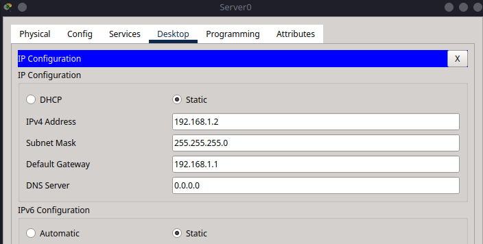
This ensures the DHCP server has a fixed IP address on the correct subnet and can communicate with the router.
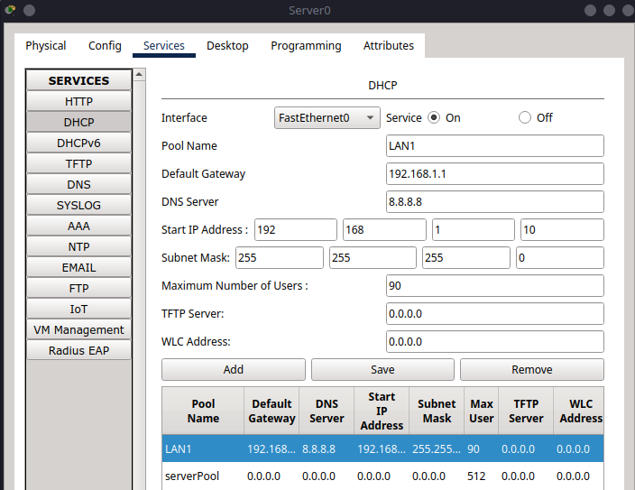
Now go to the Services tab
From the left menu, select DHCP
Make sure Service is turned On at the top
Warning
Ensure to turn on the ServerPool service in the DHCP settings, but don’t change any of its default settings.
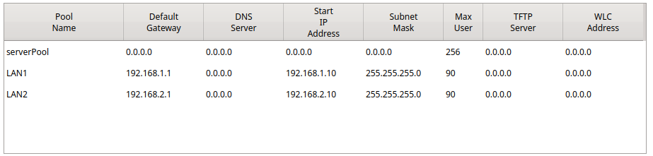
Configure the first pool (for Switch 0 / VLAN 1)-#
Pool Name:
LAN1Default Gateway:
192.168.1.1DNS Server:
0.0.0.0Start IP Address:
192.168.1.10Subnet Mask:
255.255.255.0Maximum Number of Users:
90Click Add
Configure the second pool (for Switch 1 / VLAN 2)-#
Pool Name:
LAN2Default Gateway:
192.168.2.1DNS Server:
0.0.0.0Start IP Address:
192.168.2.10Subnet Mask:
255.255.255.0Maximum Number of Users:
90Click Add
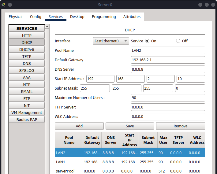
You should now see both pools listed in the table at the bottom, showing their assigned configurations.
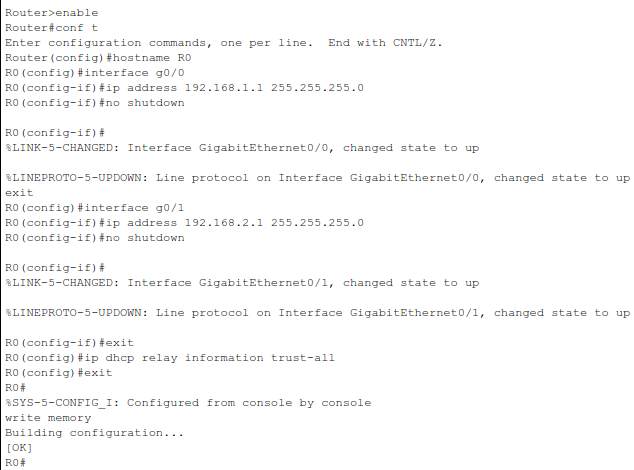
Step 4.2 – Configure Router Interfaces#
Note
We will be configuring the DHCP server to have the IP address 192.168.1.2 and we will use the ip helper-address command to forward DHCP requests from VLAN 2 to the DHCP server.
enable
configure terminal
hostname R0

interface g0/0
ip address 192.168.1.1 255.255.255.0
no shutdown
exit

interface g0/1
ip address 192.168.2.1 255.255.255.0
ip helper-address 192.168.1.2
no shutdown
exit

ip dhcp relay information trust-all
exit
write memory
Part 5 – PC Configuration and Testing#
Your network is now set up with a DHCP server and router. The next step is to configure the PCs to use DHCP for automatic IP address assignment.
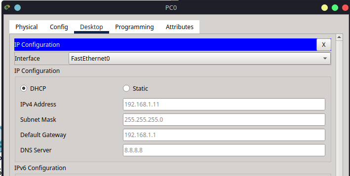
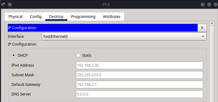
Step 5.1 – Set PCs to Use DHCP#
Click on each PC (PC0–PC5)
Go to Desktop > IP Configuration
Select DHCP (not static)
Each PC should automatically receive an IP address, subnet mask, default gateway, and DNS server.
Step 5.2 – Verify Connectivity#
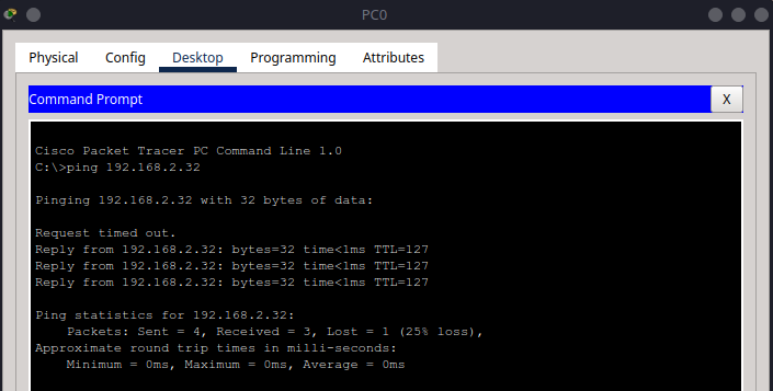
From PC0, ping PC3:
Note
Make sure to check the IP address of PC3 before pinging as it may vary based on the DHCP assignment.
ping 192.168.2.32
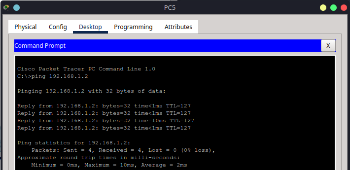
From PC5, ping the DHCP server:
ping 192.168.1.2
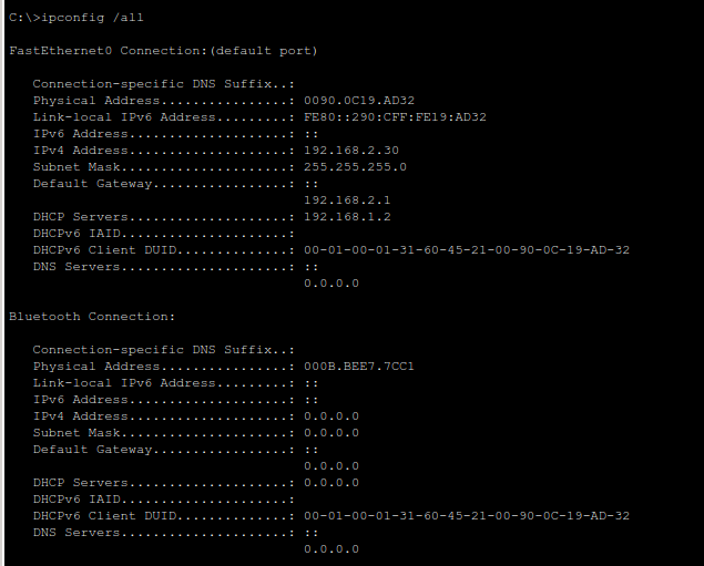
You can also run:
ipconfig /all
This displays the IP address, gateway, and DNS settings assigned by DHCP.
Summary#
In this tutorial, you:
Built a two-switch, single-router network
Connected a DHCP server to automatically manage IP addresses
Configured two IP subnets for different LAN segments
Verified automatic address assignment using DHCP
DHCP simplifies network management by removing the need to manually assign IP addresses to each device—especially valuable in larger or frequently changing networks.